
Mining display interfaces are not defined by the connector visible behind the screen. In mining equipment, the display path is a signal chain that begins with machine data, passes through an HMI computer or display controller, becomes a timed pixel stream, and returns touch input through a separate path. Each boundary has a different electrical and software responsibility.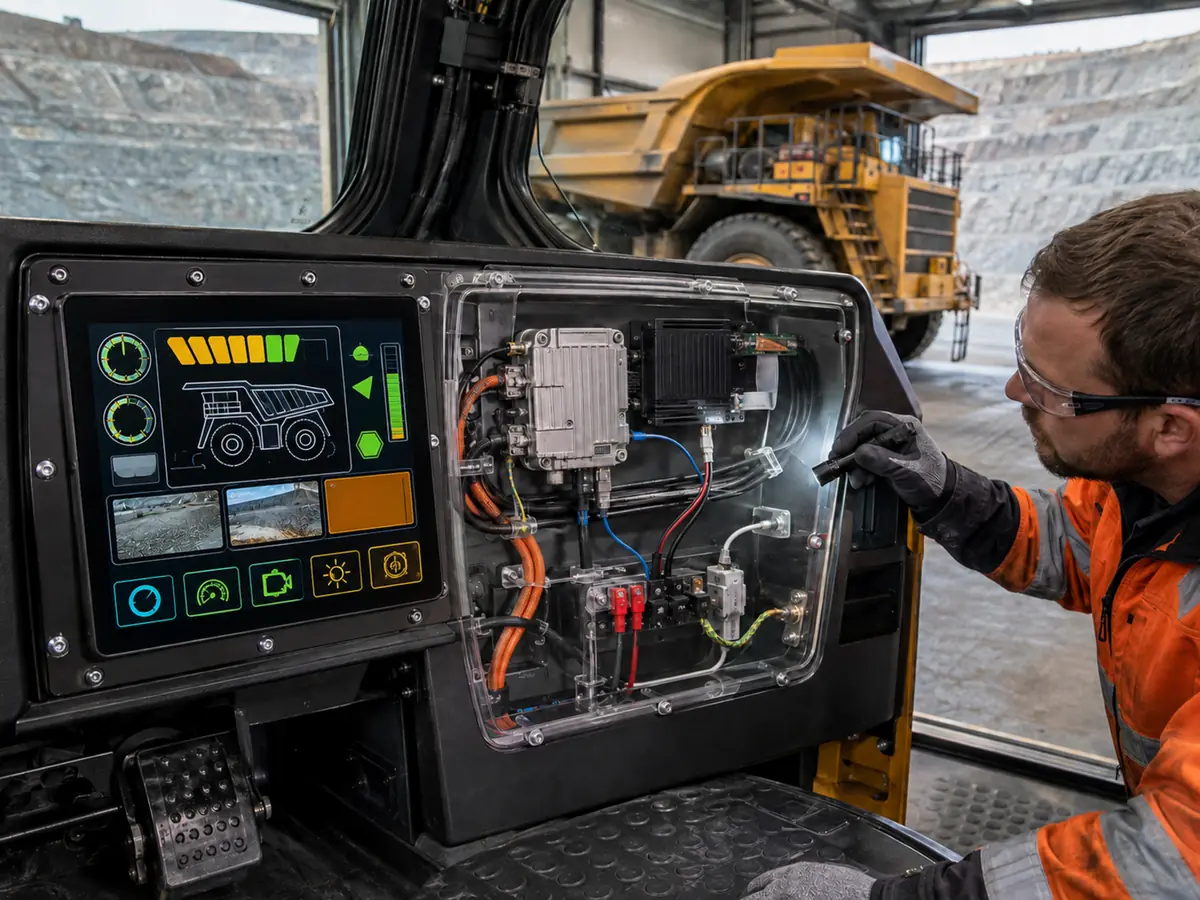
This distinction is important in haul trucks, drill rigs, loaders, crushers, conveyors, processing plants, and remote operating stations. A CAN or Ethernet network may deliver engine status, payload, alarms, or automation data to the HMI, but a bare LCD still needs a compatible native video signal. A monitor may accept HDMI or DisplayPort, yet its touch controller may communicate through USB.
Quick Answer: Mining display interfaces may use CAN, SAE J1939, industrial Ethernet, or serial communication to move machine data into an HMI controller; LVDS, eDP, MIPI DSI, or parallel RGB between an embedded host and a native LCD; HDMI, DisplayPort, DVI, or VGA between a computer and a monitor or display-controller board; and USB or I²C for touch. These interfaces operate at different boundaries and cannot be substituted by matching connector shapes. Approval requires the exact host, panel, controller, firmware, cable, power sequence, resolution, timing, touch path, startup behavior, and mine-equipment operating events.
Claim: A mining display connection is compatible only when every boundary from machine data to visible pixels and returned touch input is defined and verified.
1. How Does Mining Data Become a Visible HMI Image?
A value shown on a mining HMI may travel through several devices before it reaches the operator. For example, an electronic control unit can publish engine temperature on a vehicle network. The HMI computer interprets that message, applies validity and alarm logic, draws the gauge, and sends a frame of pixels to the LCD.
Direct answer: Machine networks carry measurements, states, commands, and diagnostic messages. HMI hardware and software convert those messages into graphics. A display output transports the finished pixel stream to the LCD or monitor, while a touch connection returns operator coordinates or input reports. Treating these as one interface hides the devices most likely to cause a fault.
What Do CAN and SAE J1939 Contribute to the HMI?
CAN-based networks can connect engine, transmission, brake, hydraulic, payload, and other controllers in mobile machinery. SAE J1939 provides a higher-layer convention widely associated with heavy-duty vehicles, but mining OEMs may also use proprietary messages and additional networks.
The HMI needs the correct database, parameter interpretation, source address, update rate, validity handling, and diagnostic rules. Receiving a CAN message does not create an image by itself; application software must decide what the message means and how it should be presented.
What Does Ethernet Change in a Mining Display System?
Ethernet may connect controllers, cameras, gateways, servers, operator stations, or condition-monitoring systems. It can carry more data than a local vehicle bus and can support remote supervision, multiple video streams, historical information, and software services.
Its presence does not mean the LCD is an Ethernet display. A computer may receive process data and camera streams through Ethernet while sending its desktop to a nearby monitor through DisplayPort. The network status and local video-link status must therefore be diagnosed separately.
Where Are the Graphics Actually Rendered?
Graphics may be rendered on an embedded processor located behind the LCD, an industrial computer elsewhere in the cab, a PLC-based HMI, a panel PC, a display-controller board, or a workstation in a remote operations room. The renderer owns the resolution, layout, fonts, alarms, scaling, and update behavior seen by the user.
Why Can a Healthy Machine Network Still Produce a Black Screen?
The data network may be operating while the graphics processor has not started, the display link has failed, the panel lacks power, the backlight is disabled, or the controller firmware does not support the panel timing. Conversely, a bright screen may display stale information after the upstream data source has stopped updating.
Fault reporting should distinguish no panel power, no backlight, no pixel link, no HMI application, no machine communication, invalid data, and frozen or stale data. A single “display fault” message is rarely enough for service diagnosis.
How Does Touch Return Through the Architecture?
Touch normally follows a path separate from video. A PCAP or resistive sensor connects to a touch controller, which reports coordinates to the host through USB, I²C, or another supported method. The application then maps those coordinates to a displayed object and requests an action through the machine-control architecture.
This round trip is examined in How Do Touchscreens Improve Mining Equipment Operation?. Replacing the LCD, changing resolution, rotating the display, or updating the host can leave video working while touch coordinates become incorrect.
Claim: Mine data, rendered graphics, pixel transport, backlight operation, and touch input are distinct functions that need separate ownership and fault evidence.
2. Which Interface Architecture Fits Each Mining Equipment Boundary?
The useful question is not which interface is best in isolation. It is where the display sits relative to the processor, enclosure, operator, service connection, and cable route. A short internal link inside a sealed console has different needs from a replaceable monitor several metres from an industrial computer.
Direct answer: Native panel interfaces fit tightly integrated embedded assemblies. Standard video inputs fit monitors and controller-based display assemblies. Machine networks feed data to the computing layer, and touch uses its own host connection. The selected architecture should minimize uncontrolled conversion stages while preserving service access and replacement feasibility.
When Does an Embedded Native-Panel Architecture Make Sense?
An embedded architecture places the host and LCD close together inside the same console, panel PC, instrument, or sealed display assembly. It can reduce external connectors and allow the equipment designer to control the cable, power, startup sequence, backlight, touch, enclosure, and software as one defined subsystem.
How Does LVDS Fit an Established Mining HMI?
LVDS remains common in installed industrial equipment and panel generations because it can carry pixel data over differential pairs between a controller and LCD. A mining machine with a long service life may continue using an LVDS host even when newer processors and panels have moved toward eDP.
LVDS compatibility depends on single- or dual-channel operation, pixel clock, color depth, bit mapping, timing, voltage, connector, pinout, and panel sequence. “LVDS” on both datasheets is only the beginning of the comparison.
When Does eDP Fit a New Embedded Design?
eDP can support newer processors and higher-resolution embedded panels with a serial packet-based link. It may be selected when the host platform and chosen industrial LCD already share a supported eDP implementation and the project can control link training, AUX communication, panel power, and backlight behavior.
External DisplayPort and eDP belong to the same standards family but occupy different physical system positions. A mining computer’s external DisplayPort connector should not be wired directly to an eDP panel without a supported architecture.
Where Do MIPI DSI and Parallel RGB Belong?
MIPI DSI can appear in compact processor-based displays where the host system-on-chip and LCD are designed together. Parallel RGB may be used in smaller or established embedded systems where the processor exposes pixel data, synchronization, and clock lines directly.
When Is a Monitor-Input Architecture More Practical?
A monitor architecture can be useful in remote-control rooms, engineering stations, fixed crusher or conveyor panels, and larger operator consoles where an industrial computer and display are separate service units. HDMI and DisplayPort are common digital choices; DVI or VGA may remain in older installations.
The monitor contains a controller that receives the standard input and generates the native signal required by its LCD. This adds firmware, EDID behavior, scaling, source detection, power, heat, and another lifecycle-sensitive board, but it can make computer replacement and external cabling more familiar.
Where Should an Interface Converter Be Located?
A converter belongs at a clearly owned boundary with controlled input, output, firmware, power, heat dissipation, mounting, and recovery behavior. It may be integrated on a controller board inside the display assembly or placed near the host, depending on signal integrity and service strategy.
A cable cannot convert LVDS to eDP, HDMI to LVDS, or a machine network into pixels without active electronics. Every active bridge adds a startup dependency and should be included in lifecycle and fault analysis.
| System Boundary | Typical Interface Examples | Information Carried | Common Fault Evidence |
|---|---|---|---|
| Machine controller to HMI computer | CAN, SAE J1939, Ethernet, serial links | States, measurements, alarms, commands, diagnostics | Stale values, missing source, invalid message, network timeout |
| Embedded host to native LCD | LVDS, eDP, MIPI DSI, parallel RGB | Timed pixel stream and link control | No image, unstable link, wrong colors, shifted or corrupted image |
| Computer to monitor controller | HDMI, DisplayPort, DVI, VGA | Digital or analog video plus configuration where supported | No source, wrong mode, scaling error, intermittent detection |
| Touch controller to HMI host | USB, I²C | Coordinates, contact state, device reports | No enumeration, false touch, wrong mapping, failure after wake |
| Power and control to display assembly | Panel supply, enable, PWM, controller power | Power sequence, backlight enable, dimming | Black image, bright blank panel, flash, delayed or fixed brightness |
Claim: Interface selection becomes manageable when each connector is assigned to one physical boundary, one data type, one owner, and one recovery plan.
4. How Should the Signal Chain Be Tested Through Mining Machine Events?
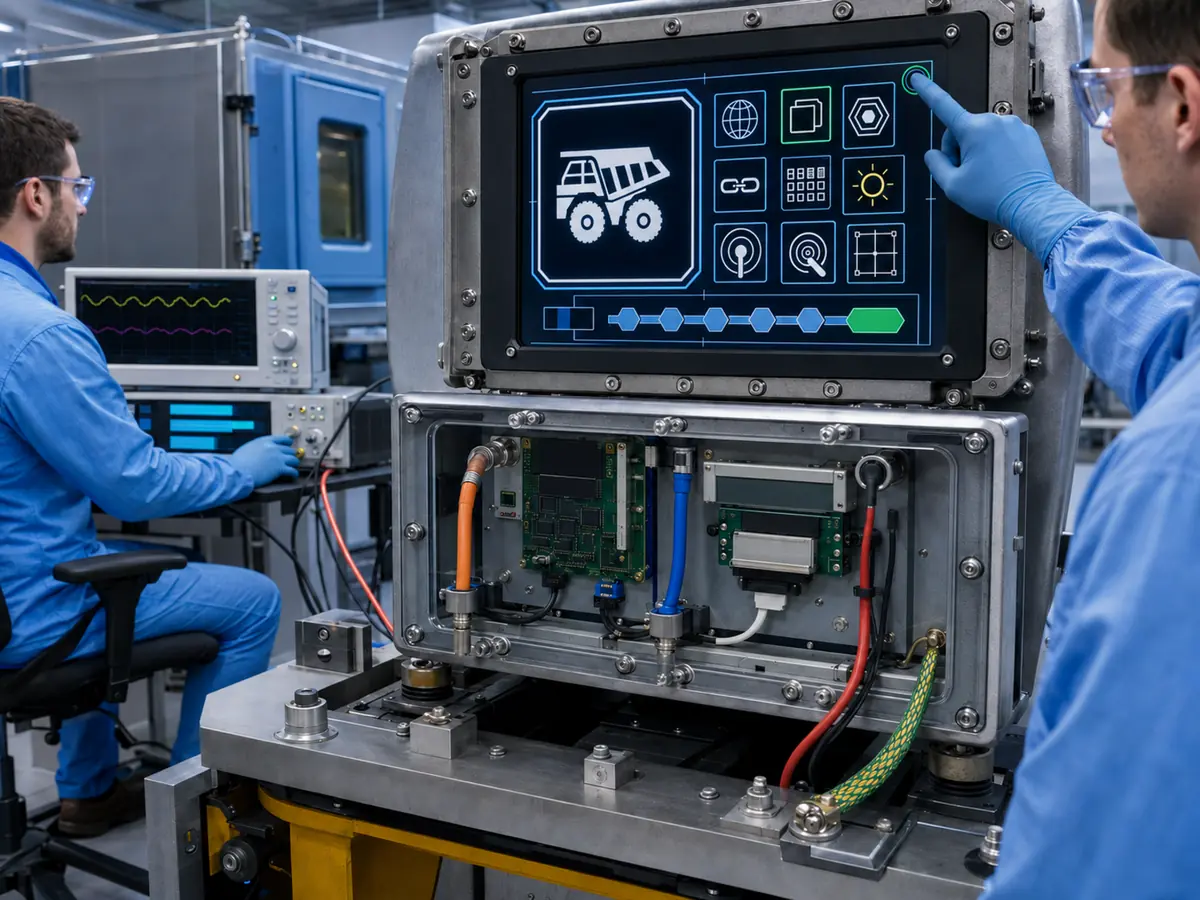
Bench operation under stable power confirms only one state. Mining HMIs pass through ignition, controller boot, engine start, machine-mode changes, communication interruptions, high electrical loads, display dimming, shutdown, and maintenance replacement. Each event can expose a different boundary failure.
Direct answer: Build an event matrix that records machine-network status, HMI application state, video-link state, visible image, backlight, touch connection, and recovery time before, during, and after each event. Test with production hardware, firmware, software, cable routing, grounding, power, enclosure, and replacement procedures.
What Should Be Observed During Ignition and Cold Start?
Record the order in which controllers, computer, display board, LCD, backlight, and touch controller become available. Check the boot image, transition into the HMI application, initial brightness, selected input, touch enumeration, and validity of the first machine values.
A screen that eventually works may still fail the operator requirement if it remains blank too long, shows an unsupported mode, presents stale stored data, or requires a manual source selection after every cold start.
How Should Engine Crank and Supply Disturbances Be Tested?
Mobile equipment power can dip or contain transients during starting and load changes. Apply the equipment-defined voltage events and observe whether the host resets, controller loses its input, backlight flashes, touch disconnects, or the image freezes.
What Happens When Machine Communication Is Lost but Video Remains?
Disconnect or interrupt each relevant data source while keeping the display link active. The HMI should identify unavailable or stale data instead of continuing to show an old value as current. Camera loss, controller timeout, partial network failure, and gateway restart may require different indications.
How Should Noise and High-Load Operation Be Included?
Operate representative motors, drives, hydraulic valves, radios, chargers, lighting, and other switching loads while monitoring link errors, image disturbance, controller resets, touch behavior, and network status. Use the intended cable routes, shields, ground bonds, and enclosure.
A stable backlight does not prove the pixels or data are stable. Record image corruption, flicker, dropped sources, repeated touch enumeration, and application communication alarms independently.
Why Should Cable Movement and Service Access Be Tested?
Apply the equipment-defined vibration and movement conditions while observing the live image and touch path. Check connector retention, strain relief, cable abrasion risk, bend radius, shield termination, and load transferred to the PCB or LCD connector.
How Should an Obsolete Panel Replacement Be Regressed?
Test the replacement against the original production event matrix rather than only comparing static image quality. Include BIOS and application start, supported modes, backlight range, touch mapping, alarms, power order, interruptions, temperature states, machine communications, and long-duration operation.
If a direct replacement does not exist, identify every changed boundary: host output, bridge board, firmware, cable, power, mechanical mounting, touch controller, resolution, or HMI layout. The affected equipment evidence can then be reviewed rather than hidden behind a shared interface name.
What Records Should Follow the Approved Interface?
Retain the host model and revision, graphics configuration, BIOS, operating system, display driver, HMI software, LCD model, controller and firmware, EDID, touch controller and firmware, cable drawings, pinouts, connector parts, power design, backlight settings, grounding, routing, test results, and approved alternatives.
The broader reason for controlling the complete display subsystem is covered in Why Does Mining Equipment Need Industrial LCD Displays?. Interface changes do not independently establish mine approval, explosion protection, functional safety, or enclosure protection.
Claim: Mining interface validation should follow machine events and verify data, pixels, illumination, touch, and recovery as separate observable states.
5. What Advantages Does XIANHENG Offer for Mining Display Interface Projects?
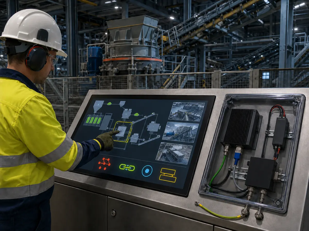
XIANHENG supports display integration for haul trucks, drilling rigs, loaders, underground machines, crushers, conveyors, screening equipment, process plants, remote operator stations, maintenance terminals, and existing equipment replacement.
Direct answer: XIANHENG can help customers define the display-side signal chain, compare industrial LCDs, match supported LVDS, eDP, MIPI DSI, RGB, HDMI, DisplayPort, DVI, or VGA architectures, and coordinate controller boards, firmware, EDID, touch interfaces, customized cables, cover glass, bonding, drawings, samples, inspection, and lifecycle planning. Final machine communication, HMI software, control authority, safety functions, enclosure, regulatory conformity, and equipment approval remain with the responsible manufacturer and approval parties.
How Can XIANHENG Review a Mining Display Architecture?
Customers can provide a block diagram showing the machine controllers, HMI computer, display output, LCD or monitor, touch path, power, cable distances, and enclosure boundaries. XIANHENG can help identify which items belong to the native-panel connection and which require a controller or standard video input.
Can XIANHENG Compare a Host and Native LCD?
The review can compare resolution, timing, interface type, channel or lane count, link rate, color depth, mapping, voltage, connector, pinout, power sequence, backlight control, cable direction, and available panel documentation.
If the host and LCD do not match directly, the options may include selecting another industrial panel, using a customized cable only when the electrical definitions already agree, or evaluating a supported bridge or controller architecture.
Can XIANHENG Support a Monitor Controller Configuration?
For supported projects, a controller can be configured around the computer input, panel output, native resolution, timing, EDID, scaling, source behavior, backlight, buttons or remote controls, connectors, power, and cable set. Firmware should be identified as part of the supplied configuration.
How Can Customized Cables Clarify Interface Ownership?
A controlled drawing can define both mating connectors, pin numbering, pair assignment, ground, shield, length, direction, label, strain relief, bend limits, and retention. Separate drawings may cover native video, standard video, touch, backlight, and power rather than combining undocumented functions in one harness.
Can XIANHENG Coordinate the Touch Path with Video?
XIANHENG can coordinate supported PCAP or resistive touch, controller firmware, USB or I²C connection, cover glass, bonding, active-area alignment, and cables with the selected LCD. Video and touch remain separately defined so that coordinate or enumeration faults can be diagnosed without changing a working image path.
How Can XIANHENG Support Existing Equipment Replacement?
Customers can provide the original LCD, monitor, controller, touch panel and cable models; datasheets; drawings; photographs; host output; BIOS and software resolution; startup symptoms; annual demand; and working samples where available.
XIANHENG can compare candidate solutions across interface boundaries, mechanics, optics, power, firmware, touch, and lifecycle. Customers can review panel starting points in the Industrial LCD Product Collection.
What Information Should Customers Send to Start?
Useful inputs include the mining machine type, operator-station architecture, host model, graphics output, original LCD, resolution, native interface, standard video input, connector and pinout, voltage, power sequence, cable length and route, backlight control, touch interface, operating system, startup behavior, communication architecture, environmental conditions, annual quantity, schedule, and service-life target.
To discuss a haul-truck display, drill-rig HMI, crusher or conveyor monitor, underground-equipment panel, remote-control display, customized cable, controller-board solution, or obsolete-interface replacement, please reach out to XIANHENG.
Claim: XIANHENG supports mining display-interface projects by defining and coordinating the display-side boundaries while preserving clear responsibility for machine data, software, control, safety, and equipment approval.


